|
Subsystem Architecture ViewsOf Imagix 4D's range of graphical layouts, the Subsystem Architecture views provide the highest level perspective. Their visual approach aids in understanding and optimizing fundamental aspects of your software's architecture - its subsystems, layers, interfaces and dependencies.
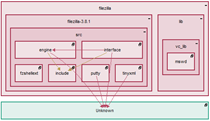
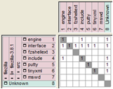
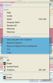
You can use the Subsystem Architecture views as soon as you have loaded your code into Imagix 4D. The first step is creating a subsystem architecture (SA) through the Subsystem Architecture wizard. As initially created, the subsystems in an SA represent either the physical (directory > file > class > function and variable) or logical (namespace / package > class > function and variable) partitioning of a software system. Once you've created an as-built SA, you can immediately start exploring it just like you do with the other views. But the SA that you've created can be considered a model. In the Subsystem Architecture Diagram, you can edit this model. By adding, deleting or moving the subsystems, you can make the SA better represent how you think about the architecture, or you can analyze the impact of architectural changes. Model changes that you make in the Subsystem Architecture Diagram can be viewed and further analyzed in the DSM. You can maintain a series of SAs in the same project. Viewing a physical-derived architecture alongside a logical-derived architecture can provide additional insight into your software as it currently exists. And having multiple modified SAs enables you to compare alternative approaches for improving your layering or interfaces. Diagram Layout and Dependency AnalysisIn a Subsystem Architecture diagram, boxes represent subsystems, and lines between boxes represent calls (and optionally set and reads) of subsystem members.Both the hierarchy and the dependencies among subsystems are reflected in the layout. If one subsystem contains a second subsystem, the box representing the second subsystem is drawn inside that of the first. Relative positioning of subsystem boxes within a containing box indicates dependency relationships. If one subsystem makes calls into the second subsystem, but is not called from the second, it is placed above the second. If two subsystems call each other, either directly or transitively through other subsystems, they are placed at the same height in the diagram. The various options under the Display menu aid in examining the dependency relationships between subsystems. Violations of strict layering occur when outbound calls (or variable usage) are made to any subsystems other than those in the next lower layer. Relaxed layering violations only occur when calls are made to higher layers. By using the Display menu items to modify which relationships are displayed, you can identify issues in your subsystem dependencies. If you find that a lot of your subsystems end up on the same level, the Display Relationship Strength option can be used to help untangle the subsystem dependencies and improve layering. You'll be able to identify which of the relationships represent only a few underlying symbols. By right-clicking on a relationship line, a context sensitive menu will appear enabling you to drill down and examine the specific functions that are involved. These functions might be targets for repackaging to bring your physical or logical partitioning into better alignment with the intended layering of your software. Modifying an ArchitectureWhen a subsystem architecture (SA) is originally created, it represents the software "as built". The subsystems in the diagram correspond to the file or namespace / package partitioning of your code. The relative positioning of the subsystems indicate the actual dependencies between the functions and variables in the portions of source code they represent.
One reason for modifying an SA would be to make it more reflective of your software's system architecture and layering. For any number of reasons, the physical or logical partitioning of your source code may no longer represent your inherent or intended architecture. By manipulating the diagram to make changes to the underlying SA model, the resulting SA can better represent the true architecture of your code. At a later point, you might choose to adjust the physical packaging of the code to better align with the modified SA. A second reason for modifying an SA would be to explore alternative layering approaches. If you're considering fine-tuning or more significant repartitioning of the layering in your software, you can experiment to see what sort of dependency issues would result from different alternatives. Managing Multiple ArchitecturesThe hierarchy within a subsystem architecture (SA), including any changes to the hierarchy that you make by modifying a diagram, is stored between sessions. When you reopen an SA in a later session, the changes you've made are restored. The layout of members within a particular subsystem is not stored nor is it available in later sessions.As you are modifying an SA, you may want to make a branch, in order to experiment with a couple of different alternatives. The best way to do this is to create a new SA through the Subsystem Architecture wizard, specifying the current modified SA as the basis for the new one. In this way, you might end up working with multiple SAs for the same software. Each of the SAs that you define are stored between sessions, until you explicitly delete them.
|